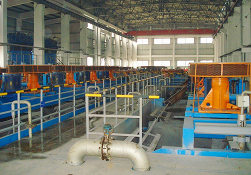
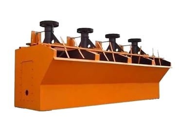
CLF type coarse particle floater belongs to inflatable mechanical mixing floater. Its impeller adopts back-inclined blade of high specific speed. The shape of the lower blade is designed to be consistent with the streamline that makes the ore slurry pass. It has a weak mixing, great amount of slurry cycle and low power consumption. Together with the tank body and the grid plate, it can fully guarantee the suspension of coarse particles and the dispersion of air. The grid plate brings a short rising distance to the coarse mineralized foam. Located in a state of shallow tank flotation, it reduces the turbulent flow of the ore slurry on the upper tank so as to establish a stable separation area and foam layer.
Product Description
This CLF type flotation machine is set with slurry suction tank, which has the ability of self-suction of mineral and medium foam mine out. and the flotation operation could have a horizontal configuration. Fan is needed in inflation. It is mainly adopted in the coarse minerals which are hard to be selected by the normal floater, as well as the normal floatation. It is suitable for the processing of non-ferrous metals, dark metals and non-metal minerals.
Product Features
1 Processing of large mineral size-the largest mineral particle could achieve 1mm.
2.Grid plate is set in the tank-stabilizes the ore slurry surface and improves technical performance.
3.Large aeration amount, good air dispersion and low power consumption.
4.Good slurry cycle-no precipitation in processing coarse mineral particles.
5.It is set with self-control system of ore slurry level-easy operation and management.
6.Coarse particle floater is set with slurry suction tank-the floatation operation could have a horizontal configuration, which saves the foam pump returned in the medium mine.
Main Technical parameters
m3 | m×m×m | kw | m3/min | KPa | m3/min | mm | kg | ||
Specification | Volume | Tank size length x width x height | Mixing motor power | Production capacity | Blower atmospheric pressure | Air consumption per tank | Feed particle size | Weight per tank | |
CLF-2 | Slurry suction tank | 2 | 1.2×1.6×1.25 | 7.5 | 0.5~2 | ≥14.7 | 0~3 | <1.0 | 1591 |
Direct current tank | 5.5 | 0~5 | 1418 | ||||||
CLF-4 | Slurry suction tank | 4 | 1.6×2.1×1.5 | 15 | 1~4 | ≥19.6 | 0~5 | <1.0 | 3002 |
Direct current tank | 11 | 0~7 | 2702 | ||||||
CLF-8 | Slurry suction tank | 8 | 1.9×2.5×1.95 | 22 | 1~6 | ≥23.5 | 0~8 | <1.0 | 5168 |
Direct current tank | 15 | 0~12 | 4654 | ||||||
CLF-16 | Slurry suction tank | 16 | 2.5×3.2×2.4 | 45 | 1~8 | ≥35 | 0~14 | <1.0 | 9230 |
Direct current tank | 37 | 0~16 | 8970 | ||||||
CLF-30 | Slurry suction tank | 30 | 3.3×4.0×3.0 | 75 | 3~15 | ≥45 | 0~18 | <1.0 | 17800 |
Direct current tank | 55 | 0~20 | 16500 | ||||||
CLF-40 | Direct current tank | 40 | φ4.2×3.6 | 75 | 4~20 | — | — | <1.0 | 24828 |